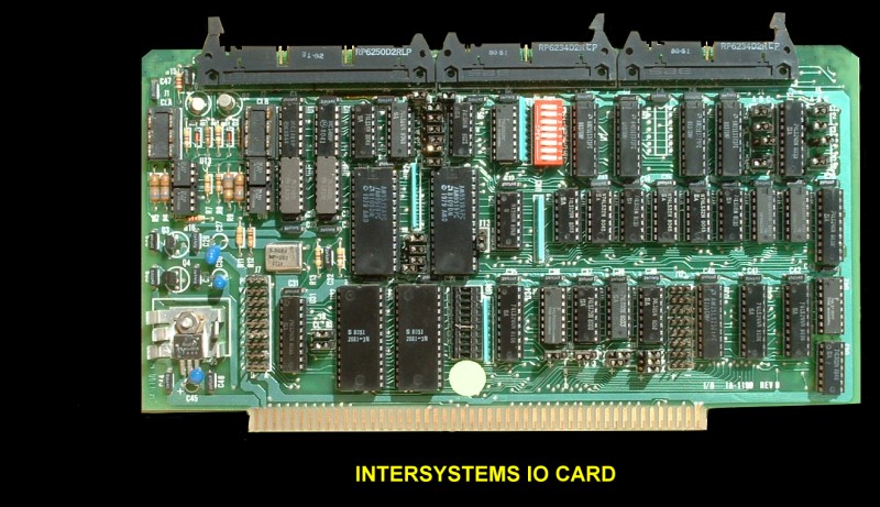
Ithaca Audio VIO card.
This was Ithaca Audio's
(later known a Intersystems) IO card.

The Intersystems Multiple
I/O board (VIO) provided the user with a versatile and powerful peripheral interface
system for the. S-100 bus.
VIO features included:-
Two independent programmable RS-232 serial ports
Independently programmable baud rates, 50 to 19200 baud.
Serial ports have current loop capability
Two 8-bit parallel output ports
Two 8-bit parallel input ports TTL
levels user definable strobes and acknowledge signals
Eight independent addressable 1-bit bi-directional
open collector control lines
An On-board programmable 16~priority
level interrupt system.
8-bit or 16-bit I/O mapped modes
or 16-bit memory mapped mode.
On board wait state generator.
All LSI fully buffered.
IEEE 692.2 S-100 standard;
2 or 4 KHz compatible.
The VIO may be jumpered
to occupy any 32 location area on any 32 location boundary in either I/O space or
memory space (but not both). The VIO contains two independent serial ports. Each
port is equipped with a set of RS-232 drivers and receivers as well as a set of
current loop drivers and receivers. Each serial port can be programmed to run asynchronously
from 50 to 19200 baud. The signals to and from both serial ports are accessible
at the leftmost 50 pin edge connector. Two 25 conductor ribbon cables coming from
this connector can each be mass terminated as a standard RS-232 connector to a terminal.
The. user may-construct a simple adaptor to configure either of the ports for attachment
to an asynchronous modem.
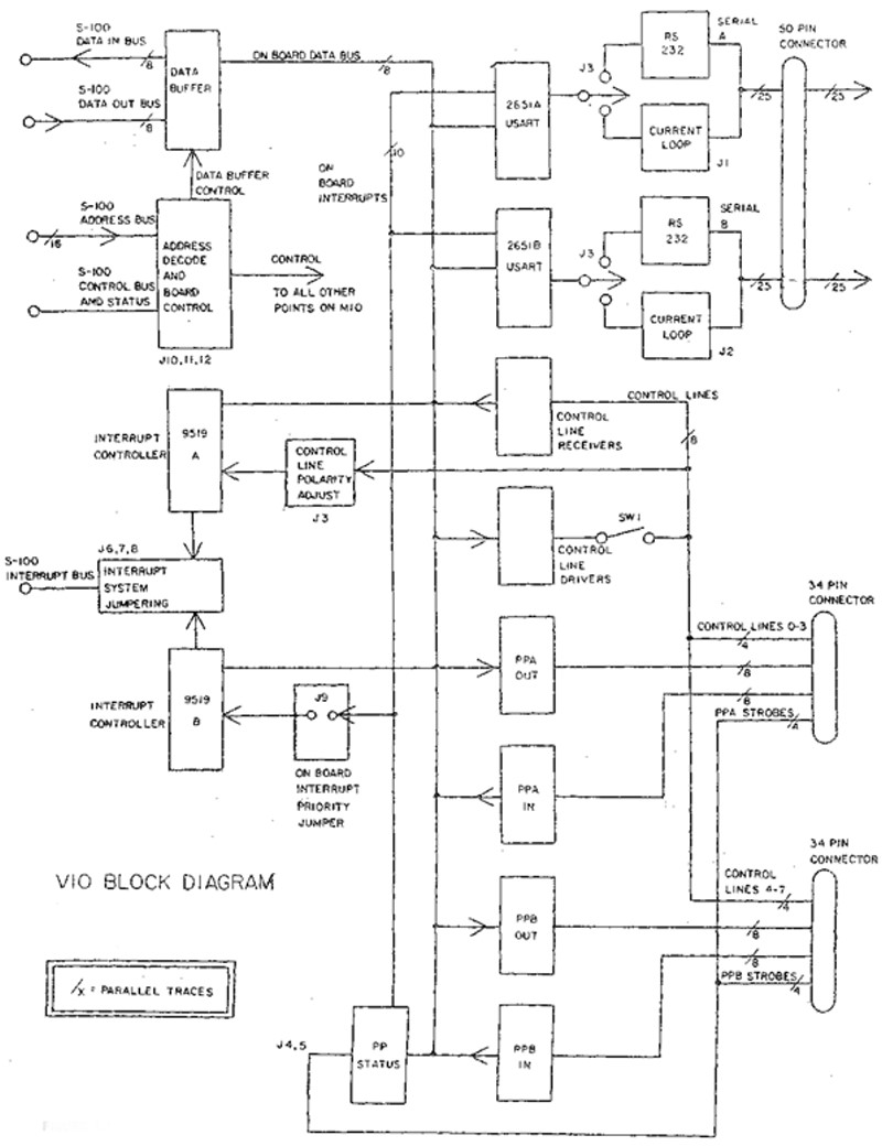
Here is a block diagram
for the card:-

The VIO contains two
pairs of TTL level 8 bit parallel ports. Each pair includes an input port with input
strobe and data received signal, and an output port with output strobe and peripheral
acknowledge signal. The active polarities of the strobes and the acknowledge signals
are shunt jumper adjustable. Parallel port pair A is accessible at the middle edge
connector. Parallel port pair B is accessible at the rightmost edge connector.
Control Lines Control
lines were provided for use as extra status lines for peripherals, lines for handling
external interrupts, or for convenient CPU control over external devices,, Each
control line is jumper selectable to function as an input line or an output line.
The VIO contains 8 independent control lines. Each control line has a separate on-board
port address which may be read from or written to. When reading and writing with
control lines, only bit 0 of the data byte is significant and represents the inverted
state of the control line. Reading a control line port always relays the state of
the control line. "Writing to a control line port always sets the open collector
control line driver; however, the user has the option whether or not to connect
each driver to the corresponding control line. This determines for each control
line whether or not the VIO board drives that line or merely receives it. Four of
the control lines are accessible on the middle edge connector and the other four
are accessible on the rightmost edge connector. Interrupts
There were two versions
of the VIO card available; the VIO-1, with interrupt controller, and the VIO~05
without interrupt controller. The interrupt controller version provides the user
with a powerful and versatile 16-input prioritized interrupt system which may be
configured to interrupt, the CPU at the occurrence of any state change in any area
on the VIO board. The interrupt system consists of two eight-input interrupt controllers
which may either interrupt the CPU independently or may be cascaded to form one
sixteen-input interrupt system. One of the eight-input systems responds to the control
lines, with user-adjustable polarity available for each line. The other eight-input
system is assigned to the serial and parallel ports, for interrupt-driven
serial and parallel data transfer.
The VIO manual can be
downloaded
here
Other InterSystems S-100 Boards
64K Dynamic RAM
8K RAM
EPROM
IA-Display
FDC
IO-Card
Series-II Z80
Z80-I
FPB
256K Dynamic RAM
16-64K EPROM
HDA
Series_III Z80
6SIO
EPROM Emulator
RTC Board
This page was last modified
on 01/08/2011


